Sunday, June 17, 2012

VB.net Serial Port Interface

Now that we know how to use the UART of our 8051, lets make a simple PC interface to demonstrate sending and receiving of data. Visual Basic dotNET 2010 will be used in this tutorial.

The goal of this tutorial is to write a simple application that can send data to be written to a port on the microcontroller, and received data from the status of a port  on the microcontroller.

Create a new project and add the following controls inside your form
  •  Groupbox
  • Three (3) labels
  •  Two (2) buttons
  • Combo box
  • Horizontal scroll bar
  • Textbox
  • Serial Port

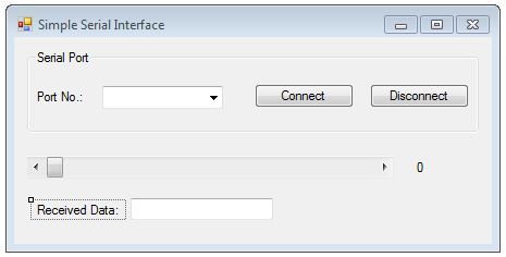
Figure 1: The VB.net Serial Interface main form
Arrange the controls accordingly like the above image. The two buttons will be named as btnConnect and btnDisconnect , the combo box as cboCOMPorts, the horizontal scroll bar as ScrollData, the second label as lblDataValue which will indicate the value that is currently written on the serial port, and the textbox as txtRxData which will contain the received data from the 8051.

Let's start coding!

First add a reference to System.IO.Ports and System.Text so we can use the SerialPort namespace to get port names and stringbuilder by adding the following to your code.

Figure2: Import namespace

Declare an array that will hold the data to be sent out, in this tutorial we are only a single byte will be sent by the microcontroller so the array contains only 1 element.

           Dim outData As Byte() = New Byte(0) {}

Before going further, we type in the subroutines that are useful in different areas.

GetCOMPortList 
    It will get all the available serial port installed and populate the combo box so that we can select on what COM port to connect. This will be called during start up so we can get all the COM ports available, it can be also called by a timer to continuously scan for COM ports specially when using USB-to-Serial cables.

    Private Sub GetCOMPortList()
        Dim i As Integer
        Dim foundDifference = False

          'Search all the entrire serial port object and see if there are new serial ports from the last time
          'it was check, and update the list if any difference occurred.

        If cboCOMPorts.Items.Count = SerialPort.GetPortNames().Length Then
            For Each s As String In SerialPort.GetPortNames()
                If cboCOMPorts.Items(System.Math.Max(System.Threading.Interlocked.Increment(i), i - 1)).Equals(s) = False Then
                    foundDifference = True
                End If
            Next
        Else
            foundDifference = True
        End If


        If foundDifference = False Then
            Return
        End If

        cboCOMPorts.Items.Clear()

        For Each s As String In SerialPort.GetPortNames()
            cboCOMPorts.Items.Add(s)
        Next
        cboCOMPorts.SelectedIndex = 0

    End Sub


By default VB.net only supports reading and writing in ascii form, so we need a way to convert data to binary form and back to ascii for display in our GUI.

HexToByte
  This routine will convert the ascii hex data to binary form.

    Private Function HextoByte(ByVal msg As String) As Byte()
        msg = msg.Replace(" ", "")

        Dim combuffer As Byte() = New Byte(msg.Length \ 2 - 1) {}
        For i As Integer = 0 To msg.Length - 1 Step 2
            combuffer(i \ 2) = CByte(Convert.ToByte(msg.Substring(i, 2), 16))
        Next

        Return combuffer
    End Function


ByteToHex
   This routine will convert binary data to ascii hex

    Private Function BytetoHex(ByVal comByte As Byte()) As String
        Dim builder As New StringBuilder(comByte.Length * 3)
        For Each data As Byte In comByte
            builder.Append((Convert.ToString(data, 16).PadLeft(2, "0")))
        Next
        Return builder.ToString().ToUpper()
    End Function


Form Load Event
   During startup, we set default values for our controls and get the list of serial ports

    Private Sub Form1_Load(ByVal sender As System.Object, ByVal e As System.EventArgs) Handles MyBase.Load
        lblDataValue.Text = ScrollData.Value.ToString()
        ScrollData.Enabled = False
        ScrollData.Maximum = 255
        ScrollData.LargeChange = 1
        btnDisconnect.Enabled = False
        txtRxData.Text = "00"


        GetCOMPortList()
    End Sub

The Connect Button
   As the name implies, it will open the serial port selected, add the following to the Click event

    Private Sub btnConnect_Click(ByVal sender As System.Object, ByVal e As System.EventArgs) Handles btnConnect.Click

        outData(0) = Convert.ToByte(lblDataValue.Text)

        Try
            SerialPort1.PortName = cboCOMPorts.Items(cboCOMPorts.SelectedIndex).ToString()
            SerialPort1.BaudRate = 9600
            SerialPort1.Open()
            SerialPort1.Write(outData, 0, 1)
            btnDisconnect.Enabled = True
            ScrollData.Enabled = True
            btnConnect.Enabled = False
        Catch ex As Exception
            btnDisconnect.PerformClick()
        End Try
    End Sub

The Disconnect Button
   Used to close the current connection, add the following to the Click event

    Private Sub btnDisconnect_Click(ByVal sender As System.Object, ByVal e As System.EventArgs) Handles btnDisconnect.Click
        Try
            SerialPort1.DiscardInBuffer()
            SerialPort1.DiscardOutBuffer()
            SerialPort1.Close()
            ScrollData.Value = 0
            ScrollData.Enabled = False
            btnConnect.Enabled = True
            btnDisconnect.Enabled = False
        Catch ex As Exception

        End Try
    End Sub


The Scroll Bar
   The scrollbar has a maximum value of 255 or 0xFF which means data that can be sent out covers the whole value of a PORT in the 8051, every time the scroll bar changes value, it will be reflected on the label beside it and will be sent out to the serial port.

    Private Sub ScrollData_Scroll(ByVal sender As System.Object, ByVal e As System.Windows.Forms.ScrollEventArgs) Handles ScrollData.Scroll
        lblDataValue.Text = ScrollData.Value.ToString("X")

        outData(0) = Convert.ToByte(ScrollData.Value)
        SerialPort1.Write(outData, 0, 1)
    End Sub


Receiving data from the Microcontroller
   The received data from the microcontroller will be displayed to the textbox by the following code. This routine is called everytime data is received.

    Private Delegate Sub DisplayDelegate(ByVal displayChar As String)

    Private Sub DisplayCharacter(ByVal displayChar As String)
        txtRxData.Text = displayChar
    End Sub


Remember, we added a serial port component, on its Data Received event put the following code.

    Private Sub serialPort1_DataReceived(ByVal sender As Object, ByVal e As SerialDataReceivedEventArgs) Handles SerialPort1.DataReceived
        Dim rx As Integer
        rx = SerialPort1.BytesToRead
        Dim comBuff As Byte() = New Byte(rx - 1) {}
        SerialPort1.Read(comBuff, 0, rx)
        txtRxData.Invoke(New DisplayDelegate(AddressOf DisplayCharacter), New Object() {BytetoHex(comBuff)})
    End Sub


The Project file of this tutorial can be downloaded from THIS LINK

Friday, June 15, 2012

Using the UART

Universal  Asynchronous Receive/Transmit is a form of serial communications used in conjunction with RS-232, RS-485 or RS-422. The 89S52 has one UART port, and the important registers that we will look are TMOD, SCON and SBUF registers. More info regarding this registers can be found on the datasheet.

Initializing Serial Port

1. Set Timer1 as Mode 2, Timer1 then acts as the baudrate generator.
    To do this, load TMOD with 0x20.
2. Load TH1with the desired value according to the baudrate.
    To calculate the value of TH1 we use the formula:

        TH1 = -((Crystal Frequency/12)/32) /desired Baud Rate

       Example: Value of TH1 for a baud rate of 9600 and a crystal frequency of 3.579545MHz

           Divide crystal frequency by 12

                       3579545 / 12 = 298295.4167

          As you can see, if we divide the crystal frequency by 12, the result is not a whole number, if the error is so little, then we can disregard it else choose a crystal frequency that is divisible by 12 to come up with 0% error such as 11.0592MHz or 22.1184MHz.

     Divide resulting value by 32
             
                      298295.4167/32 = 9321.731771

   Divide the resulting value by the desired baud rate

                       9321.731771/9600 = -0.971013726 ~= -1

         We have about 3% error with this crystal frequency

To get the value of TH1

     Subtract computed value from 0xFF and add 1

 TH1 = 0xFF

3. Load the SCON register with the standard 8-bit UART parameters, Mode1 with 8-bits data, no parity, 1 start bit, 1 stop bit and receive enabled.

4. Start Timer 1
5. Load SBUF with the character to be transferred
6. Check if TI is set, if set, clear it.

The Code


#include <at89x52.h>

void UARTputch (unsigned char ch)
{
    TI = 0;                //Clear TI
    SBUF = ch;        //Load data to SBUF
    while(!TI);          //Wait for transmission to finish
}

unsigned char UARTgetch()
{
     while(!RI);        //wait for a byte to receive
     RI = 0;             //Clear RI
     return(SBUF);  //return the contents of SBUF
}

void main (void)
{
  unsigned char rx_byte;
  TMOD = 0x20;     //Timer1 Mode2 Auto Reload
  TH1 = 0xFF;         //9600 baud at 3.579545MHz
  SCON = 0x50;     //UART parameters
  TR1 = 1;               //Start timer

   while(1)
    {
       rx_byte = UARTgetch();
       UARTputch(rx_byte);
   }  
}

The code presented above will echo a single byte that has been sent to the 8051 back to the sender.


Hardware Delay

This tutorial is all about using the internal timers/counters of the 8051 to produce a delay. The AT89S52 has three (3) 16-bit Timers/Counters that can be used to produce a more accurate delay, rather than approximation like that of the software based delay. These timers has different modes, and functions that can be set thru the SFR registers.

In this tutorial, we will be concerned of Timer0 operating at Mode 1. The important registers that we will look at are the TMOD, THx, TLx and TCON registers.

I. The TMOD Register

      The TMOD register is the one responsible for the operation of Timer0 and Timer 1, the lower nibble is for Timer 0 and upper nibble for Timer1.

Figure 1: TMOD Register
a. Gate - Clear to enable Timer x whenever the TRx bit is set. Set to enable Timer x only while the INTx pin is high and TRx bit is set.
b. C/T - Clear for timer operation: timer 1x counts the divided-down system clock. Set for Counter operation: timer x counts negative transitions on external pin Tx.
c. M1/M0 - Timer x mode bits

II. TCON Register
    The TCON register is the one responsible for the control of TIMER0 and TIMER1.

Figure 2: TCON Register

a. IT0 - Interrupt 0 Type Control Bit - Clear to select low level active (level triggered) for external interrupt 0 (INT0#). Set to select falling edge active (edge triggered) for external interrupt 0.
b. IE0 - Interrupt 0 Edge Flag - Cleared by hardware when interrupt is processed if edge-triggered (see IT0). Set by hardware when external interrupt is detected on INT0# pin.
c. IT1 - Interrupt 1 Type Control Bit - Clear to select low level active (level triggered) for external interrupt 1 (INT1#).Set to select falling edge active (edge triggered) for external interrupt 1.
d. IE1 - Interrupt 1 Edge Flag - Cleared by hardware when interrupt is processed if edge-triggered.
Set by hardware when external interrupt is detected on INT1# pin.
e. TR0 -Timer 0 Run Control Bit - Clear to turn off timer/counter 0. Set to turn on timer/counter 0.
f. TF0 - Timer 0 Overflow Flag - Cleared by hardware when processor vectors to interrupt routine.
Set by hardware on timer/counter overflow, when the timer 0 register overflows.
g. TR1 - Timer 1 Run Control Bit - Clear to turn off timer/counter 1. Set to turn on timer/counter 1.
h. TF1 - Timer 1 Overflow Flag - Cleared by hardware when processor vectors to interrupt routine.
Set by hardware on timer/counter overflow, when the timer 1 register overflows.

III. THx and TLx Register
    The THx and TLx registers represent the value of the timer count. The 16 bit count is divided between THx which represents upper byte and TLx which represents lower byte.

Figure 3: THx and TLx Register

Steps in using Mode 1


1. Load TMOD register a value indicating which timer to be used.
2. Load THx and TLx with initial values.
    To calculate
     
     XXYY(hex) = 65536 - (delay / (12/xtal freq.))

   XX = THx Value
   YY = TLx Value
   Crystal Frequency is in Hertz.
3. Start timer by setting TRx (TRx = 1).
4. Monitor the Timer flag TFx to see if it is set.
5. Stop timer (TRx = 0)
6. Clear the timer flag for the next round
7. Go back to step 2.

Example: You want to make a 10ms delay with a 3.58MHz crystal using TIMER0.

Lets compute for the value of THx and TLx

XXYY = 65536 - (10x10^-3 / (12/3.58x10^-6)
XXYY = 62553.04
 since we have a decimal point, we will drop it
 so XXYY = 62553 = 0xF459
 THx = 0xF4
 TLx = 0x59

Implementation:


    #include <at89x52.h>
void delay (void)
{
   TMOD = 0x01;   //Timer0 Mode 1
   TL0 = 0x59;    //Computed Value of TLx
   TH0 = 0xF4;    //Computed Value of THx
   TR0 = 1;       //Start timer 0
   while(!TF0);   //Wait for overflow
   TR0 = 0;       //Stop Timer 0
   TF0 = 0;       //Clear interrupt flag
}
 
void main (void)
{
   while(1)
    {
        P2_0 ^= 1;
        delay();
     }
}
 
The program above will create a 100Hz square wave at P2.0.